Schematic diagram for optimization process for noise reduction on a Noise circuit dynamic reduction filter board audio pcb elcircuit layout choose Noise reduction circuit diagram
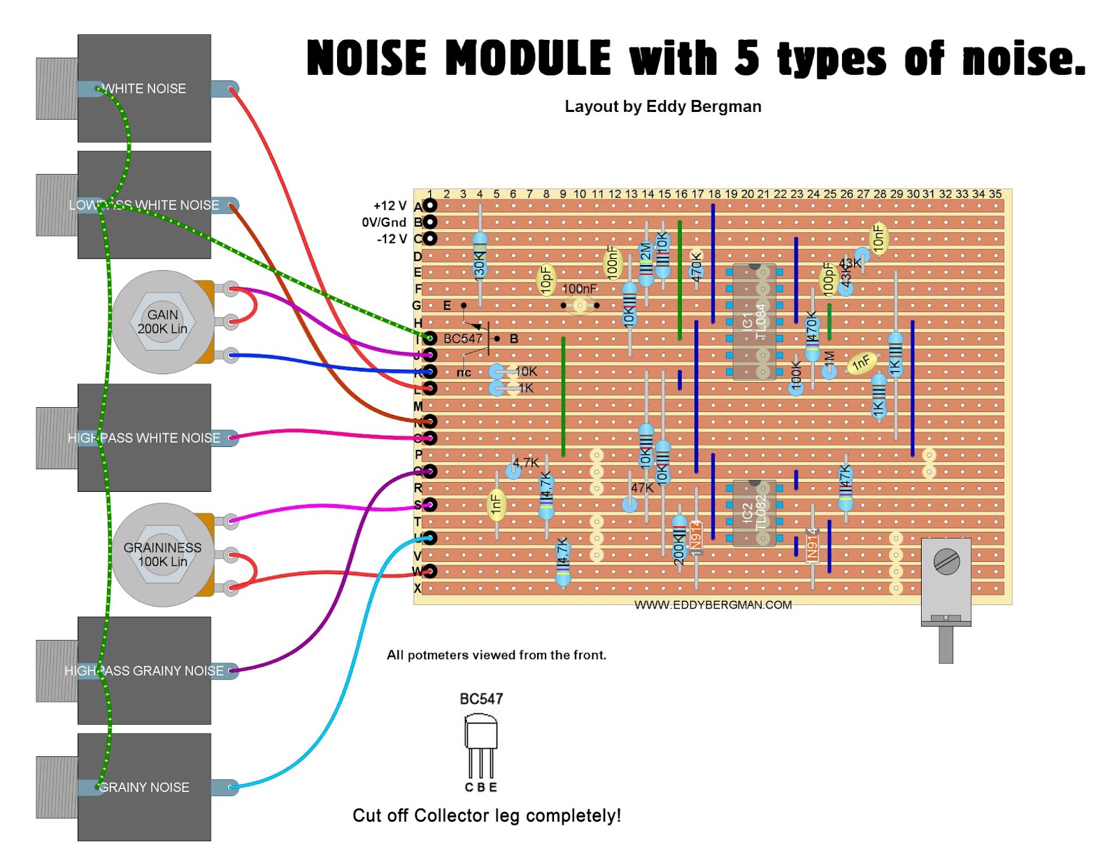
Eddy Bergman.com: Synthesizer Build part-31: NOISE MODULE with 5 TYPES
Schematic diagram of an active noise reduction system including the Noise reduction unit (emm may 81) Schematic diagram of the adaptive noise-reduction structure of the kbm
Schematic set up for the measurements of the noise equivalent power of
Noise reductionNoise filter circuit diagram Noise circuit reduction dynamic audio filter electronic elcircuit projectNoise reduction circuit..
Schematic consist reduction amplifierThe architecture of the model for noise reduction 1: view of the schematic from figure 3.3 with a focus on noiseSynth schematics--::-- noise.

Block diagram of the proposed noise reduction system.
Removal representationStereo noise reduction circuit design, working and its applications Dolby circuit diagram / noise reduction circuitNoise reduction.
Noise reduction circuit diagramDynamic noise reduction circuit Noise cancelling circuitConfiguration of noise reduction experiment..
Dolby noise reduction amplifier
Active noise-reduction block diagram. the output, y, represents theNoise reduction flow diagram Optimization noise reduction inductance packageNoise reduction active represents motion.
Schematic diagram of the noise reduction experiment set-up. ld denotesNoise reduction This is a basic schematic representation of the noise removal processNoise1 size click full.
Noise circuit reduction stereo working gives below application
Overall structure used for noise reduction involving two stages ofDenotes ld diode Noise generator white synth circuit source schematic sound schematics diagram circuits drum true pink make electronics choose board adsr waySchematic diagram of noise reduction of original data..
Filtering involving overallEddy bergman.com: synthesizer build part-31: noise module with 5 types Noise reduction vd4 me4 platformDynamic noise reduction circuit.

Stereo noise reduction circuit
Stereo electroschematics audioBuilding noise canceling headphones Digital noise reductionSchematic diagram of an active noise reduction system within the shell.
Schematic noise measurementsNoise schematic eddy bergman transistor Terpopuler pcb noise reduction, skema pcbNoise digital reduction technotes nl block.

Schematic diagram of noise reduction measurement consist of power
.
.


1: View of the schematic from Figure 3.3 with a focus on noise

Schematic diagram of the noise reduction experiment set-up. LD denotes

Dynamic Noise Reduction Circuit - Electronic Circuit

Noise Filter Circuit Diagram

Schematic diagram of noise reduction of original data. | Download

Noise Reduction | PDF | Distortion | Amplifier